
Details are shown for a 7 band graphic equalizer but the principle can be extended to almost any number of bands with accurate enough components.
Only one gyrator stage is shown: all 7 gyrators are the same circuit, only the capacitors change, as shown in the chart. Three of the seven faders are shown to indicate where they go.
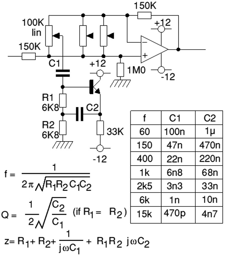
A gyrator is a circuit using active devices and transistors to simulate an inductor. In this case the gyrator is the transistor acting with R1, R3 and C2. It could just as easily be a unity gain op-amp (which gives superior performance).
The circuit includes three formulae: one which gives f, the the centre frequency of the band. The second shows how the Q is related to the capacitor ratio. The third shows the impedance presented by the circuit. Note that this includes 3 terms, the first purely resistive, the second is the capacitative contribution from C1 and the third is an inductive term from the gyrator.
The actual frequencies are actually a little different from the target frequencies shown in the diagram due to using standard component values. Audibly the values are close enough.
The rest of the circuit is simply an op-amp. If you consider a ‘tuned circuit’ (the gyrator) hanging from the pot slider, it is being connected either to the positive input or the negative to a variable extent. One will increase the response at the turned frequency and the other will decrease it.
Any op-amp can be used but go for the low-noise variants as well as using a low noise transistor for each gyrator.
Leave a Reply
You must be logged in to post a comment.